Skip to content
Vehicle Design & Dynamics

Formula Student vehicle dynamics

Vehicle dynamics for a Formula Student car, 3rd at Formula Bharat 2020
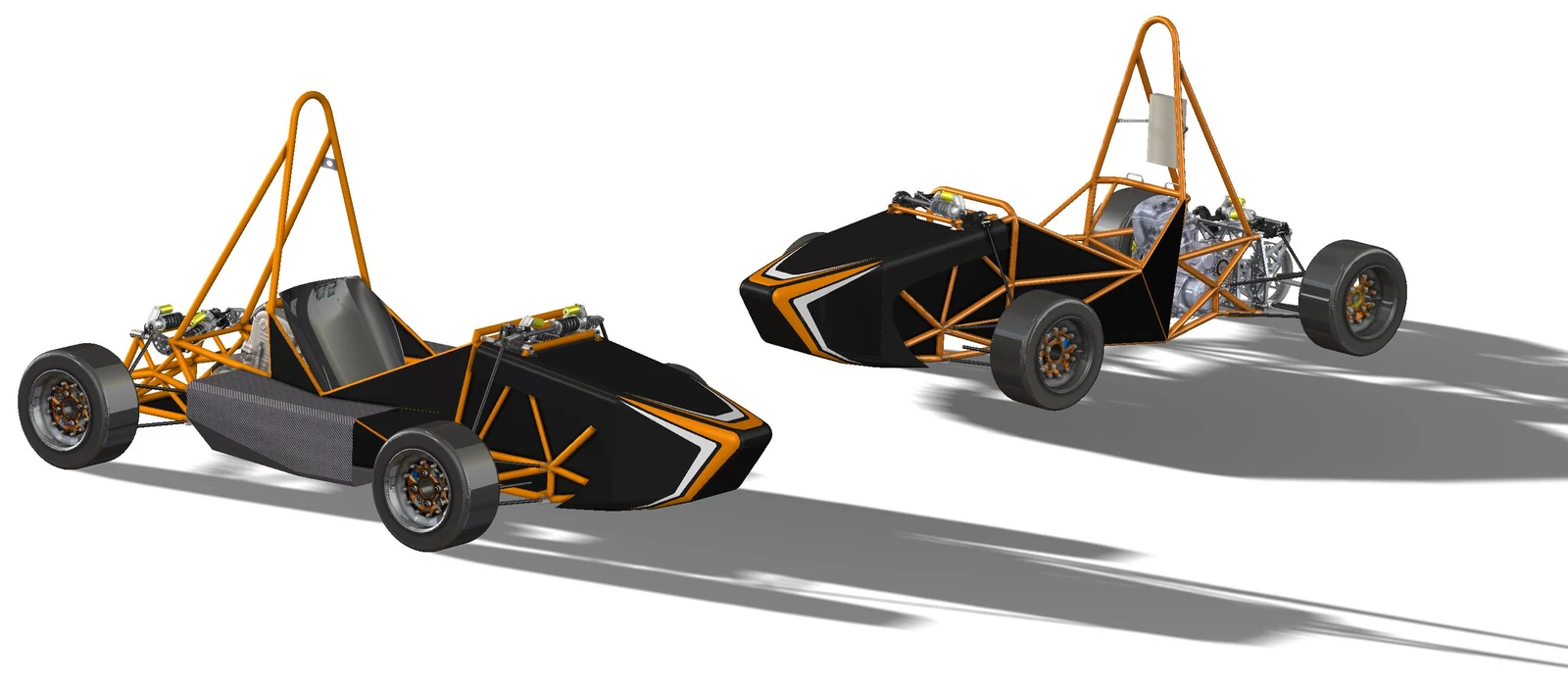
CAD render of two Formula Student cars side by side: on the left the 2020 car with its tubular rear frame, on the right the 2021 design with a plate rear bulkhead carrying the rear suspension and drive
The team's 2020 car and the 2021 design, in CADKindCAD renderSourceGTU Motorsports, Formula Student

Two seasons on a race car's dynamics, from tyre data to track testing; in the second I ran the vehicle-dynamics group. The team won Acceleration and Endurance at Formula Bharat 2020 and placed 3rd in Engineering Design at Formula Bharat 2021, held virtually.

Organisation
GTU Motorsports
Period
Apr 2019 to Mar 2021
Role
Vehicle Dynamics Engineer
cut from already-light suspension parts
~3 kg
Certificate of participation, Formula Bharat 2020, 22 to 26 January 2020, Kari Motor Speedway, presented to Darshak S. Panseriya, 01 GTU Motorsports, Gujarat Technological University
Formula Bharat 2020, Kari Motor Speedway: certificate of participationKindCertificate, sponsor logos and barcode removedSourceOrganiser's certificate

Tyre data and kinematics

When the team's attempt in MATLAB stalled, I analysed the Formula SAE Tire Test Consortium data in Excel: how much grip the tyres gain or lose at each level of weight transfer, and set the suspension to manage it.

Built the full-vehicle kinematic model in MSC Adams from scratch, because no template covered the new geometry. The Excel workflow stayed with the team, so later team members could reuse it.

Fy,max​ [N]Fz​ [N]Fz​ − ΔFz​Fz​Fz​ + ΔFz​grip losttwo tyres at Fz​after transfer, Fz​ ± ΔFz​, and their meanμ = Fy,max​ / Fz​ falls as Fz​ risesFy,max​ [N]Fz​ [N]Fz​ − ΔFz​Fz​Fz​ + ΔFz​grip losttwo tyres at Fz​after transfer, and the meanμ = Fy,max​ / Fz​ falls as Fz​ rises
Why weight transfer costs gripKindRelation, not dataSourceDrawn for this siteNoteTyre data are licensed to Tire Test Consortium members and are not shown.

The suspension layout

The team's first decoupled heave and roll suspension, which gives heave and roll their own spring and damping, was designed for both seasons and ran on track in 2020.

The roll damper is mounted so that it compresses in roll one way and extends in roll the other. A damper works both ways, but a spring only pushes back in compression, so I designed a cage that always compresses the spring-damper, whether the rocker pulls it apart or pushes it together.

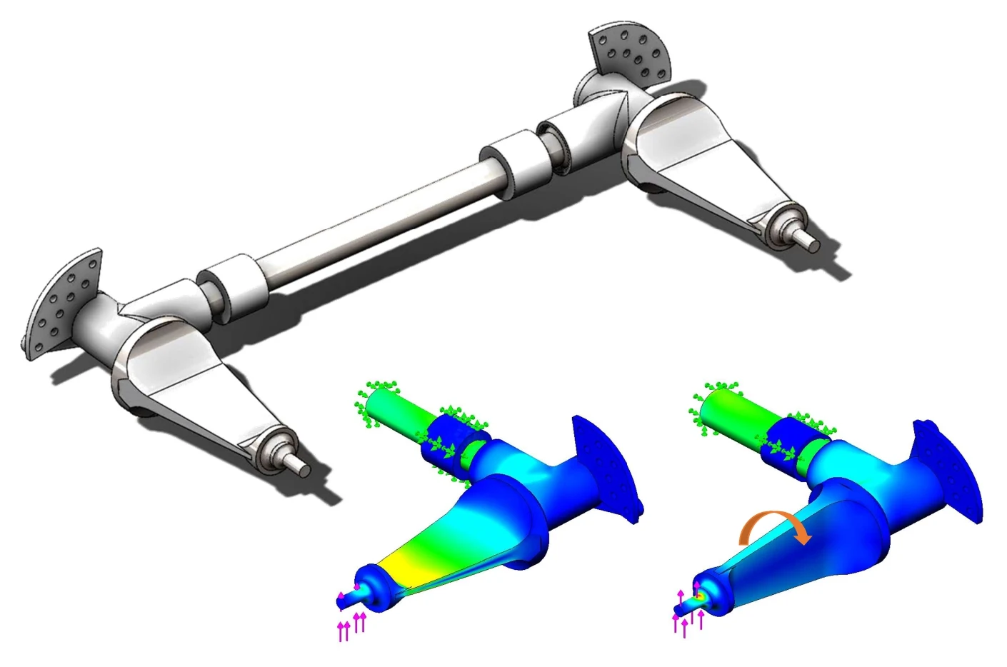
A blade-type anti-roll bar designed so roll stiffness can be retuned in minutes. The blade bar and the caged roll spring are two ways to give the car its roll stiffness: the bar for a layout with plain dampers on the rocker shafts, the cage for a roll spring-damper. One or the other, never both.
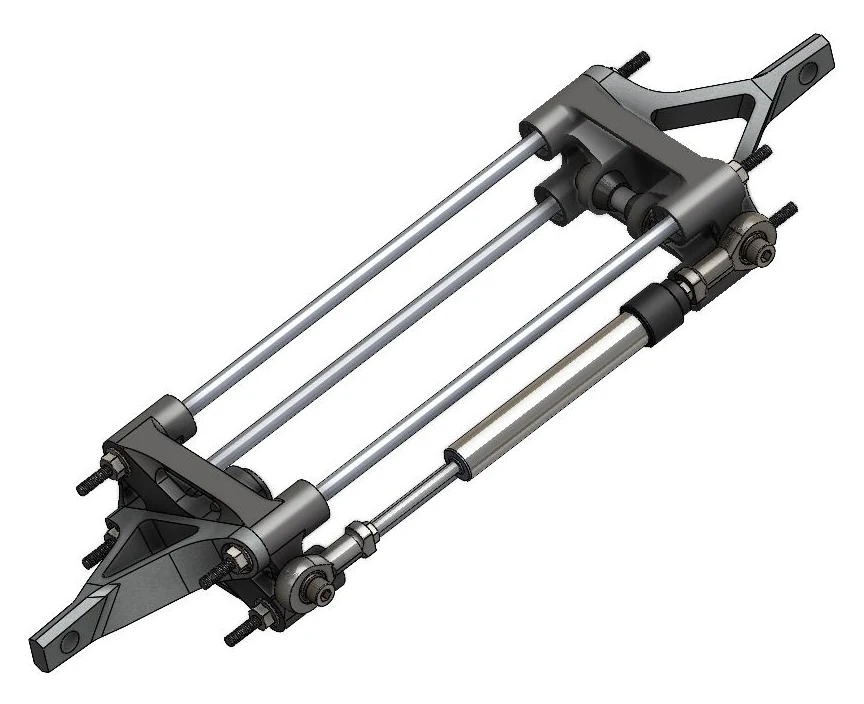
CAD render of the damper cage: two end yokes joined by four guide rods, with a spring-damper unit and rod ends held between them
The damper cage on the roll unit, in CADKindCAD renderSourceGTU Motorsports, Formula Student
CAD render of the blade anti-roll bar, a torsion tube in two sleeves with a tapered blade arm at each end; below, two FEA results of one blade arm, held at the bar and loaded at the blade tip, with the blade flat and turned
Blade anti-roll bar in CAD, and one blade arm in FEA, flat and turnedKindCAD render; FEA, stress contour, scale removedSourceGTU Motorsports, Formula StudentStresslowhighNoteFixed at the bar, loaded at the blade tip. Run at three blade positions; the two extremes are shown.

Parts and structures

About 3 kg taken out of already-light parts in many small steps: wheel centres, damper cage, damper extension shaft, rocker shafts. Every major component checked in FEA across 5 to 10 load cases.

With the chassis department I co-designed the rear bulkhead: a water-jet plate assembly that carries the suspension and drivetrain mounts. I designed the welding fixtures.
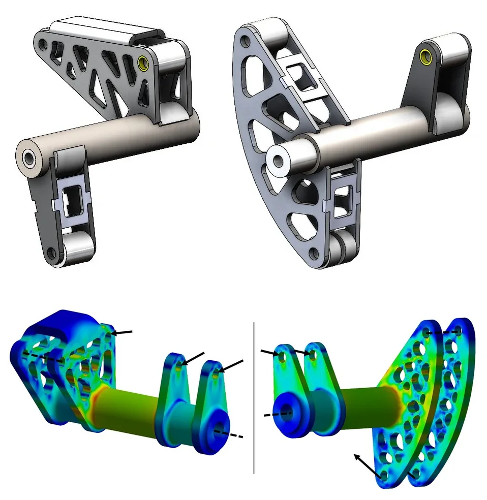
Above, CAD renders of the two rocker shaft assemblies side by side: a triangular lattice-cut rocker plate on a shaft, and a curved lattice-cut rocker plate on a shaft that ends in a clevis. Below, the same two in FEA: blue low stress, red high, highest where the rocker plates meet the shafts.
The heave and roll rockers on their shafts, in CAD and in FEAKindCAD render; FEA, stress contour, scale removedSourceGTU Motorsports, Formula StudentStresslowhighNoteLoad case: the maximum heave and roll spring forces at the element eyes; arrows mark the applied loads. The CAD and the FEA model differ in detail at the shaft ends.

Testing

Wrote the validation plan: damper potentiometers, steering angle, IMU and wheel speed. Setups tuned on track, every session logged.

1234×45×41234×45×4
Sensor planKindSchematic, principle only, not to scaleSourceDrawn for this siteNote① damper potentiometers, heave and roll units ② steering angle ③ IMU, near the centre of gravity ④ wheel speed, at the uprights ⑤ scale pads, for corner weights.

The second season

Ran the vehicle-dynamics group: two engineers, design reviews, integration with chassis, powertrain, steering and braking. Represented the group in Engineering Design judging, and trained team members in ANSYS and Adams.

Fact sheet

Competition
Formula Bharat 2020 and 2021
Stack
SolidWorks, ANSYS, MSC Adams, Lotus, Excel
All the Formula Student figures, on Dk Vehicle Studio